Transmitter
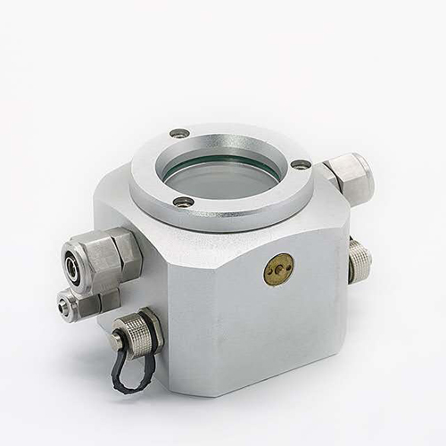
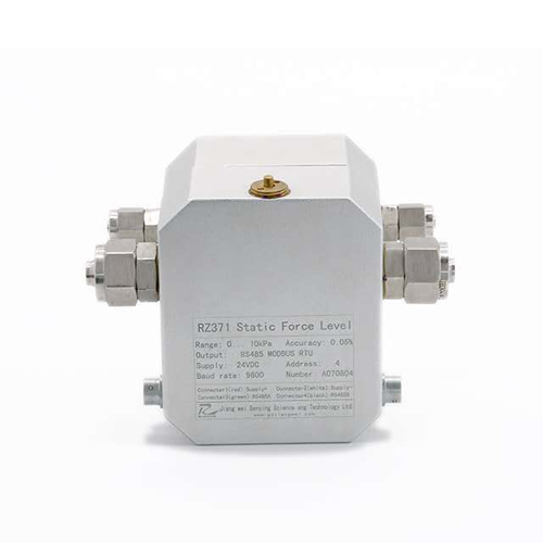
RZ370 Static Force Level
Product Details
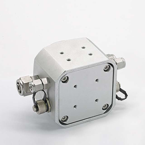
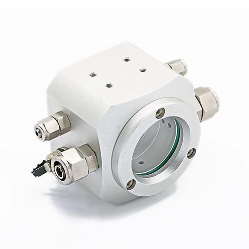
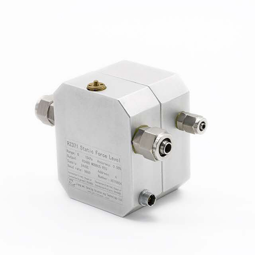
RZ370 differential static force level consists of Al-Mg alloy shell, super high accuracy silicon piezo resistance sensor and intelligent digital compensation circuit module. Settlement system consists of many same sensors. Liquid storage tanks connected with each other via gas and liquid tubes. The datum point is placed on a stable horizontal base point. Pressure difference will be caused by the measuring points’ variation from datum point. Distance variations between measuring and datum point will be calculated then.
RZ370 static force level can be applied mainly to monitor vertical displacement and gradient of large scale tank, dam, nuclear power plant, high-rise, pit, tunnel, bridge, subway, etc. Static force level system is generally installed on a pier or contour that has the same height as the measuring point. It utilizes integrated modular automatic measuring unit to acquire data and fulfil observation automatically via wired or wireless connection with computer. It is a high accuracy on line observation system and supports automatic networking transmission.
l Anodized Al-Mg alloy, the shell has beautiful appearance, small size and easy installation;
l Digital temperature compensation, resolution is 0.01mm;
l Output RS 485 MODBUS digital signal, supports 128 channels network;
l High protection level, adapt to a variety of complicated conditions
Classical applications:
u Operating railway and subway tunnel settlement observation;
u Pit, dam, building, bridge, etc. settlement observation
Supply Ability
300 PCS / day
Lead Time
Quantity(Pieces) | 1 - 200 | 200 - 500 | >500 |
Est. Time(days) | 2~3 | 3~5 | 6~10 |
Technical Specifications
Functional parameters | |
Measurement range | 0~3kPa…0~20kPa |
Pressure specification | Positive pressure |
Temperture sensor | A class PT100 thermal resistance |
| Accuracy level | ±0.5%FS, ±1%FS (Test condition: temperature 20±5℃, air pressure 86~106kPa, humidity 45%RH~75%RH, no vibration and electro-magnetic interference) |
| Ability of over pressure | 3 times of measurement range |
| Working temperature | -40~80℃ |
| Temperature compensation | -20~50℃ |
Temperature deviation | ≤0.25%FS (Within the temperature compensation range) |
Annual stability | <0.1%FS/Year (Typical); <0.2%FS/Year (Maximum) |
Electrical parameters | |
Power supply | 0~28VDC |
Power current | <10mA |
Output signal | RS485 |
Communication | Modbus RTU |
Communication distance | 1000m, maiximmum parallelconnection quantities: 255 |
Service life | >1 million times pressure measurement circle |
Electrical connections | Four core waterproof YC8 aviation socket (V+, GND, 485A, 485B) |
Physical parameters | |
Product material | Diaphragm: stainless steel 316L Housing: Anodized Al-Mg Seal ring: NBR (Nitrite Butadiene Rubber) Release valve: H62 copper |
Protection level | IP65, IP67, IP68 |
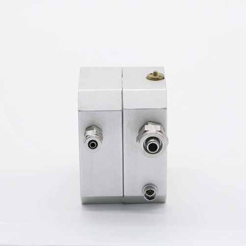
Liquid connection interface | 12mm pneumatic locking joint |
Gas connection interface | 6mm pneumatic locking joint |
Installation method | horizontal bracket installation |
Surroundings parameters | |
Atmospheric pressure | 60~110kPa |
Environment humidity | ≤95%RH |
Storage temperature | -40~120℃ |
Vibration | Under the condition of 10Grms, 20~2000Hz variation lower than 0.1%FS |
Impact | 20g, 10ms impact the variation is lower than 0.5%FS |
Outline Dimensions
Unit (mm)
")
Electrical Connections
Plug assembling and connection schematic diagram:
Terminal | Two-line 4-20mA | Three-line 0/1-5V | RS 485 Digital output | Cable indication |
Terminal 1 | Power supply + | Power supply + | Power supply + | Red line |
Terminal 2 | Power supply - | Power supply - | Power supply - | White line |
Terminal 3 | -- | Output +(blue line) | RS 485A | Blue(green) line |
Terminal 4 | -- | -- | RS 485B | Black line |
Schematic diagram for electrical connection of 4-line 485 digital signal output:
")
Selection Guilde
")