Transmitter
RZ23T Series Pressure Transmitter
Product Details
RZ23T series pressure transmitters use imported ceramic capacitor sensor, no filled liquid, no contamination for processing, solid ceramic diaphragm, excellent anti-corrosion and anti-abrasion performance. When overloaded, the diaphragm can avoid being by sticking to the bottom of ceramic lining. When pressure goes back to normal, the performance of the transmitter goes back to normal too because of its strong ability of anti-overload and anti-impact, micro-integration structure that integrates sensor and flexible circuit inside a stainless shell. Signal processing uses imported conditioning circuit that has high-stability, high-efficiency, better linearity (<0.01%). All products experienced strict test and burn-in screening:
l Reversed polarity and transient overcurrent/overvoltage protection, in accordance with EMI protection requirements.
l Accurate zero-point/range calibration via outer calibrator.
l Multi-specification signal for output connection: 4-20mA, 0-5V, 0.5-4.5V, etc.
l Wide range of measurement.
l Stainless steel structure.
l Mutli-type of pressure connection.
l Protection level: IP65.
l Explosion-proof product, acquired explosion-proof certificate with indication Ex ia II C T6.
RZ23T integrates superior sensor element, excellent electrical circuit and advanced packaging technology all in one. It’s the ideal pressure measurement product in mechanical and hydraulic area using.
Classical applications:
u Automobile brake system, lubrication oil pressure measurement.
u Hydraulic/pneumatic equipment: air compressor, injection molding machine, automobile lubrication oil, etc.
u Pressure measuring for central air-conditioner, auto air-conditioner, etc.
Supply Ability
500 PCS / day
Lead Time
Quantity(Pieces) | 1 - 200 | 200 - 500 | >500 |
Est. Time(days) | 2~3 | 3~5 | 6~10 |
Technical Specifications
Functional parameters | |
Measurement range | 0~1Mpa…0~5Mpa |
Pressure specification | Positive pressure, negative pressure, absolute pressure. |
Accuracy level | ±0.5%FS, ±1%FS (Test condition: temperature 20±5℃, air pressure 86~106kPa, humidity 45%RH~75%RH, no vibration and electro-magnetic interference) |
Ability of over pressure | 1.1~6 times of measurement range. (Varied from different measurement ranges) |
Working temperature | -40~80℃ |
Zero wander | ≤0.02%FS/℃(doubled in proportion when lower than 100kPa) |
Full range drift | ≤0.02%FS/℃(doubled in proportion when lower than 100kPa) |
Annual stability | <0.1%FS/Year (Typical); <0.2%FS/Year (Maximum) |
Frequency response | Sensor<1ms; transmitter≤15ms |
Service life | >1 million times pressure measurement circle |
Electrical parameters | |
Power supply | 24VDC 12VDC(selected) 5VDC(selected) |
Current load | <(U-10)/0.02Ω [U: power potential] |
Output signal | Two-line 4~20mA, 0~5V, etc. |
Dielectric strength | 500V no breakdown |
Insulation resistance | >500MΩ |
The effect of fluctuation of power supply on output | <0.003%FS/V |
Explosion-proof indication | Ex ia IIC T6 |
Requirements for electrical connection and wire diameter | HSM connector(wire diameter Φ4.5~Φ6.5mm) or 1m cable |
Physical parameters | |
Applicable medium | Liquid and gas which would not react to the structure material (sensor and seal material) |
Sensor foundation material | Stainless steel, etc. |
Sensor seal material | Fluororubber, ceramics, adhesive, etc. (no seal material for welding structure) |
Protection level | IP65, IP67, IP68 |
Weight | Approximately 150g~10kg(varied from sub-types) |
Surroundings parameters | |
Atmospheric pressure | 60~110kPa |
Environment humidity | ≤95%RH |
Storage temperature | -40~120℃ |
Vibration | Under the condition of 10Grms, 20~2000Hz variation lower than 0.5%FS (only effective for general specification which the vibration limitation is 15g) |
Impact | After 100g, 10ms impact the variation is lower than 0.5%FS (only effective for general specification which the impact limitation is 120g) |
Electromagnetic/RF interference | Under the condition of 10~300MHz and 15V/m, the error is lower than 0.5%FS |
Outline Dimensions
Note:
1. Unit (mm)
2. Despite the difference of connection dimension, the outer dimension may be different; customized products please consult us.

Electrical Connections
Plug assembling and connection schematic diagram:
Terminal | Two-line 4-20mA | Three-line 0/1-10V | Digital output |
Terminal 1 | DC +(red line) | DC +(red line) | DC +(red line) |
Terminal 2 | DC –(black line) | DC –(black line) | DC –(black line) |
Terminal 3 | -- | Output +(blue line) | RS 485 +(blue line) |
Terminal 4 | -- | -- | RS 485 -(yellow line) |
1: Schematic diagram for electrical connection of 2-line 4~20mA analog signal output:

2: Schematic diagram for electrical connection of 3-line 0-10V DC (0/1-5V DC) analog signal output:

3: Schematic diagram for electrical connection of 4-line 485 digital signal output:

4: Schematic diagram for electrical connection of HART protocol liquid level transmitter:

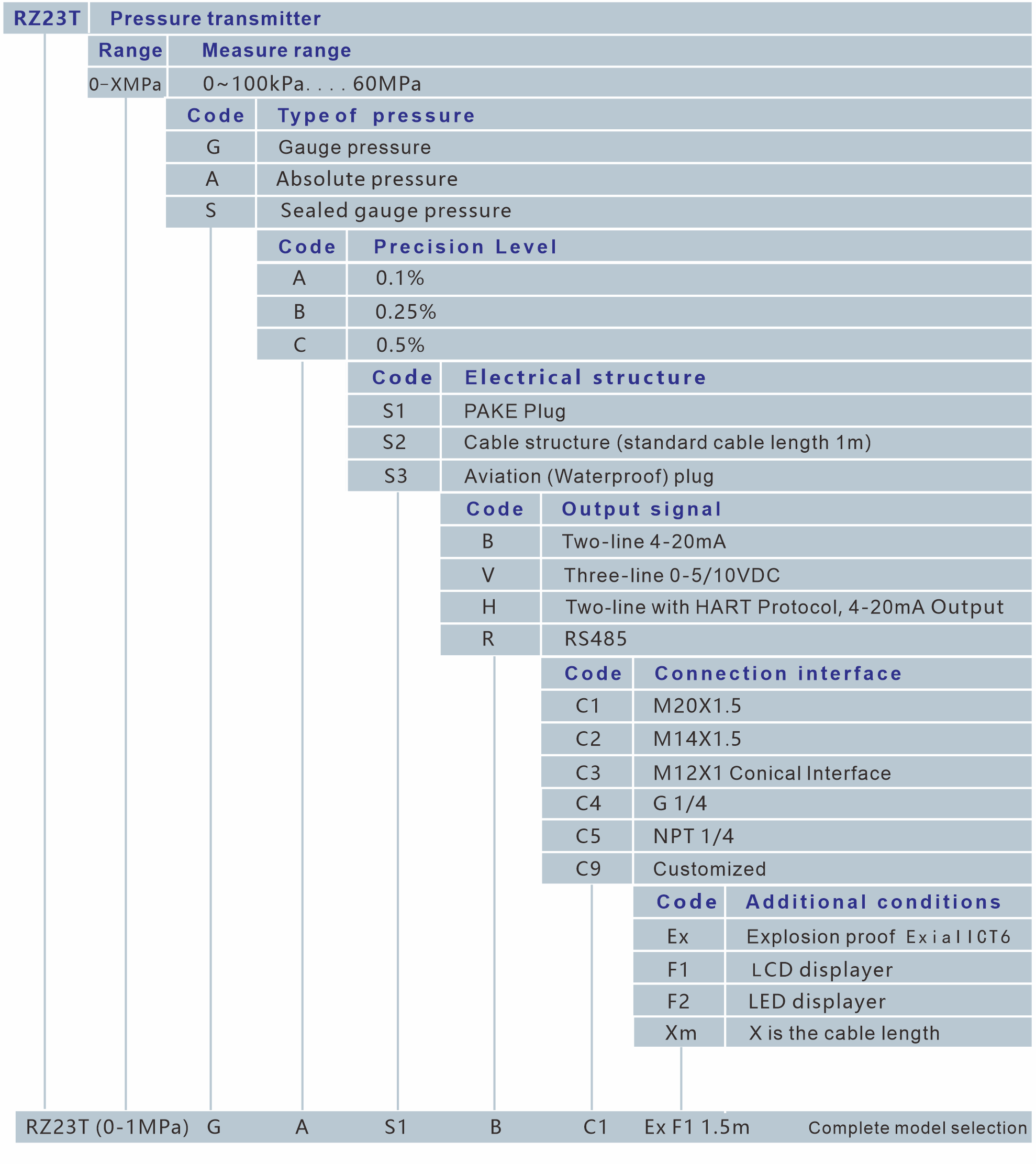
Selection Guide

Note:
1. Special requirements please consult our company and mark them in the order document in detail.
2. The application medium must be compatible with the selected product.
3. Please note that the explosion-proof product does not include the digital displayer.
4. If order transmitter with LCD or LED meter, power supply cannot be lower than 15V DC.
5. Customized connector type and size can be noted beside the selection model.


