Transmitter
RZ18 Series Explosion-proof Temperature Transmitter
Product Details
RZ18 series explosion-proof temperature transmitters are industrial temperature measurement instruments which have high measurement accuracy, wide application range, 4-20mA standard current signal output and excellent function-prize ratio.
RZ18’s electrical shell which is made by all-explosion-proof and water-proof aluminum alloy, and integrates strong anti-interference signal processing electrical circuit in super-micro structure, can provide extra assurance for reliable temperature measurement in complicated industrial environment.
RZ18 chooses imported class A PT100 or thermocouple as sensible measurement element which has high reliability and service life. Signal processing uses a steady and high efficiency electronic calibration technology which can fulfill zero point and measurement span calibration through internal potentiometer.
RZ18 integrates superior sensor element, excellent electrical circuit and advanced packaging technology all in one. It’s the ideal temperature measurement product in industrial and mineral area using.
Product features:
l Reverse polarity protection and instantaneous over-current and over-voltage protection, comply EMI protection requirements.
l Can fulfill high accuracy calibration for zero point and measurement span through internal potentiometer;
l The output signal has a variety of standard specifications such as: 4~20mA, RS485, HART protocol 4~20m can be connected to the display meter.
l Wide range of measurement.
l All stainless steel structure, protection grade IP65.
l Explosion-proof product, acquired explosion-proof certificate with indication ExdIIBT6.
Classical applications:
u Temperature measurement of water, gas, oil, acid, alkali, salt, organic solvent etc.
u Temperature measurement and control system for industrial pipelines and containers.
u Temperature measurement of hydro-pneumatic equipment such as aircraft, loaders, compressors, etc.
Supply Ability
500 PCS / day
Lead Time
Quantity(Pieces) | 1 - 200 | 200 - 500 | >500 |
Est. Time(days) | 2~3 | 3~5 | 6~10 |
Technical Specifications
Functional parameters | |
Measurement range | -50℃…200℃ |
| Accuracy level | ±0.25%FS, ±0.5%FS,±1%FS |
Time constant | IV(<10 seconds), III(10~30 seconds), II(30~90 seconds), I(90~180seconds) Note: 1. Time constant means that when the medium’s temperature needs to be measured stepped from A to B, the time that the temperature-sensing element changed from A to [A+(B-A)x63.2%]; 2. The absolute value of (B-A) must meet: ≥70℃ 3. The temperature-sensing element’s response time is in connection with conduit’s material, diameter, wall thickness, insertion depth, installation mode, medium speed, etc. |
Ability of over pressure | 1.1~6 times of measurement range. (Varied from different measurement ranges) |
Working temperature | -40~80℃ |
Pressure withstand performance | 0.2MPa~100MPa (optional) |
Stability of range upper and lower limit | ≤(75% of maximum permissible errors corresponding to accuracy level) |
Electrical parameters | |
Power supply | 24VDC 12VDC(selected) |
Current load | <(U-10)/0.02Ω [U: power potential] |
Output signal | Two-line 4~20mA |
Dielectric strength | 500V no breakdown |
Insulation resistance | >500MΩ |
The effect of fluctuation of power supply on output | <0.003%FS/V |
Explosion-proof indication | Ex id IIB T6 |
Requirements for electrical connection and wire diameter | Green terminals(wire diameter Φ4.5~Φ6.5mm) or stainless steel pipe joint(internal thread M16X1.5) |
Physical parameters | |
Applicable medium | Liquid and gas which would not react to the structure material (sensor and seal material) |
Sensor foundation material | Stainless steel (SS304), etc. |
Sensor seal material | NBR, fluororubber, tetrafluoroethylene, adhesive, etc. (no seal material for welding structure) |
Protection level | IP65, IP67, IP68 |
Surroundings parameters | |
Atmospheric pressure | 60~110kPa |
Environment humidity | ≤95%RH |
Storage temperature | -40~120℃ |
Vibration | 20gRMS, under condition 202kHz, difference <0.5%FS |
Impact | 100g, 10ms impact, difference <0.5%FS |
Electromagnetic / RF interference | Under the condition of 10~300MHz and 15V/m, the error is lower than 0.5%FS |
Outline Dimensions
Note:
1. Unit (mm)
2. Despite the difference of connection dimension, the outer dimension may be different; sensor length (L) and diameter (D) please consult manufacture when order.

Electrical Connections
1: Schematic diagram for electrical connection of 2-line 4~20mA analog signal output:

2: Schematic diagram for electrical connection of 4-line 485 digital signal output:

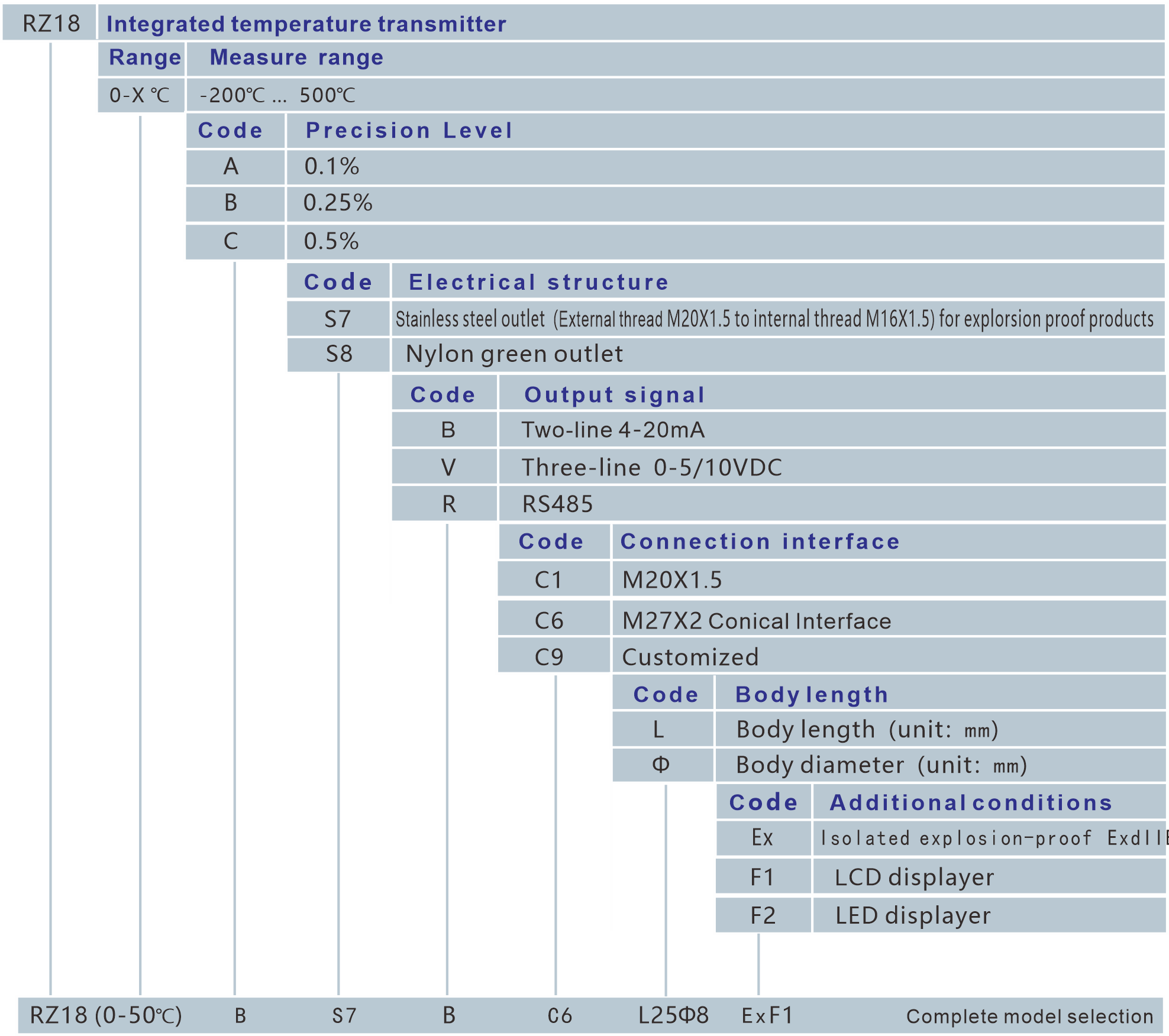
Selection Guide


